When you have a system that allows all the information to be centralized on a screen, the monitoring and control of the images becomes much easier.
by *RGB SpectrumMulti-signal display processors are used in control rooms to present visual elements and data, as well as facilitate group decision-making. This solution can be a multiple viewfinder with a single screen or a multi-screen video wall. The processor supports the selection of the inputs, the size and position of the windows in which they are displayed.
To facilitate understanding, greater emphasis can be achieved by adjusting the size and position of windows, as well as by juxtaposing related information. The cursor on the screen allows you to control the processor and can also be used as a pointer. However, conventional systems offer limited mechanisms for the control of source images; what is needed is an application that combines control of the display space and source inputs without interruption. The techniques described in this article represent a solution to this problem.
As described below, a complete system consists of a control computer, image sources, and display processor connected over a network or networks. Image sources can include computing devices, as well as keyboard- and mouse-controlled video sources, such as PTZ (pan, tilt, zoom) cameras or digital video recorders (DVRs). A source computer can be any computer-based device that provides video, including data, images, or streaming from live sources. In each of the control equipment a remote data access agent configured to communicate with the control computer through an IP network is installed, the latter is used to configure and manipulate each of the connected devices.
Let's look at some of the most common monitor, keyboard, and mouse (KVM) applications, such as GoToMyPC® and pcAnywhere®. Such applications rely on IP networks for video transport and control. However, the low video resolution and slow response time are typically due to the limited bandwidth available on IP networks. This, on the other hand, is not a problem for the transmission of keyboard and mouse input signals, since the bandwidth requirements for keyboard and mouse control are minimal. However, for optimal video quality, remote computers can connect to the display processor through a video interface, such as a digital visual interface (DVI).
Multiple images, a single screen
RGB Spectrum has developed a solution that can be used with its multiple viewfinders and display wall processors, called the KvM Integrated Control System. This system is a hybrid that combines direct video connection and IP connection for keyboard and mouse; hence the change in the nomenclature of the KVM industry standard to "KvM". Video inputs are routed directly to the processor and synchronized with control signals transmitted over the IP network. This hybrid solution provides high bandwidth for video signals and flexible data transfers for keyboard and mouse signals. Video over IP technology may also be used in cases where direct video connection is not possible due to distance or other reasons.
Figure 1 is a graphical representation showing an example of an integrated visualization and control system. The control of IP networks can be one of the many possibilities, with Ethernet being the most common.
The display processor, control computer, and source computers have unique IP addresses. A Remote Data Access Agent (RDA) is installed on each of the control computers. To create a secure session, passwords and encryption systems for private keys and public keys are used between the source computer and the control computers. Mechanisms such as Transport Layer Security (SSL), Secure Sockets Layer (SSL), and Secure Shell (SSH) can also be used to provide greater security.
A complete system also requires an effective user interface to control the display processor and source computers. A particularly suitable system would offer:
- An on-screen cursor that allows you to move around the entire viewing area.
- Unified control of the display processor and source computers using a single mouse, without the need to use other devices, physical or otherwise, such as icons or display menus.
- A keyboard for data entry.
Working togetherIn the implementation of the KvM-integrated control system, switching between the video processor control and the source computers is as simple as clicking the mouse.
1. The on-screen cursor allows you to control the video processor and the source computers.
to. Switching between the video processor control and the source computers is simple.
b. Optical nuances on the screen: The size and shape of the cursor indicate whether it controls the video processor or a source computer based on the position of its X and Y coordinates. For example, at first the cursor is activated in video processor control mode and appears on the screen as a large arrow.
2. A single mouse controls the display processor and source computers without the need to use other devices and without requiring a screen space dedicated to icons or menus.
to. The mouse controls a source computer when the cursor is located inside the window in which the images are displayed. Outside the window the mouse controls the display processor. The operating mode changes depending on the position of the mouse.
b. When the mouse is in display processor mode, the cursor can also be used as a pointer and/or to control the size and position of the screen windows. For example, when the cursor is located inside a window, you can click the left mouse button and hold it down to drag the window to a new position on the screen. If you locate the cursor on the edge or corner of the window, you can resize the window.
c. When the cursor is placed inside a window, just click with the mouse to change control mode and display the computer in the window. A smaller cursor indicating the mode change will now appear. In addition, the keyboard functions of the control computer can be used. It is also possible to operate multiple computers: when the cursor moves to a window, it controls the computer displayed in that window.
d. Moving the cursor out of a window reverts to display processor mode, which allows you to control how the source images are displayed. (Figure 2).
3. A single keyboard is sufficient for all source computers. This keyboard also allows you to track the status of the mouse. In short, the user interface is very simple and intuitive. A single mouse and keyboard is all you need.
In short, the RGB Spectrum solution offers a unified system for viewing and controlling computers and devices operated by a computer. By using a direct connection for video in addition to IP control, the hybrid solution allows you to benefit from the advantages of both types of connectivity and high-quality video transport and flexible control. The video quality, as well as resolution, response time, and frame rate, are noticeably superior to those of other video-over-IP based solutions. The system works with a single mouse that controls the on-screen cursor and an optional keyboard for data entry. This hybrid system is complemented by the user interface for uninterrupted, real-time control and unmatched response time.
The KvM-integrated control system is an option available for MediaWall® multi-display video walls and RGB Spectrum SuperView® multi-signal display processors.
* RGB Spectrum® designs and manufactures videographic and multimedia hardware subsystems.
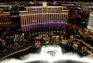 For this edition of AVI LATINOAMÉRICA magazine, the company NEC brings us a successful case study advanced in the MGM Mirage in which the experience of visitors to Las Vegas was improved through the implementation of an effective digital signage system.